Bang For Your Buck Prototypes
While LPWAN (Low-Power, Wide-Area Network) companies are busy establishing their networks, a developer’s innovative new prototype can steal the IoT limelight. My name is Clemente, Intern at Ingenu and Electrical Engineering Student at the University of San Diego. I am currently building prototypes with the RPMA® (Random Phase Multiple Access) Dev-Kit for demonstrations at upcoming Ingenu hackathons. This post will share my process of transforming a trip to the hardware store and the RPMA Dev-Kit into a proof-of-concept prototype. Before getting into my prototyping process, I want to refer you to my colleague’s article about how simple it is to get started with the RPMA Dev-Kit.
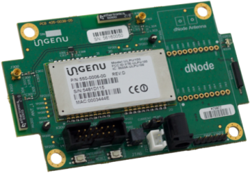
 Max Gibbons’ blog series “An Idiots Guide to RPMA Development” demonstrated how just about anyone can take the RPMA Dev-Kit and make an IoT proof-of-concept prototype. In summary, Max used a humidity & temperature sensor connected to an Arduino that forwarded its readings to the RPMA module. I encourage everyone to check out Max’s series first and see that the RPMA Dev-Kit is as simple as working with a command line interface. His article did a great job demonstrating RPMA in action; however, the RPMA Dev-Kit acted only as a communication module in his example. The light I will cast on the RPMA Dev-Kit is its ability to act as a standalone development board. Furthermore, I implore you to read the material in the RPMA Dev-Kit Starter Pack and find out all the built-in functionality it has. For my example prototype, I will use one of the most simple and useful features built into the Dev-Kit called “rising or falling edge detected alarms”.
The edge detection feature on the RPMA Dev-Kit, a working home fire alarm, and some simple electronics were all the materials I needed to build an RPMA fire alarm. In an effort to keep things simple, I started my project by making a few good design decisions. I asked myself, what signal am I going to use from the fire alarm to alert the Dev-Kit? Does that signal need modification to work with the Dev-Kit? Lastly, how will I connect and configure my board to a fire alarm? For the first question, I decided to use the fire alarm’s reliable speaker output signal. To get access to the fire alarm’s signal for analysis, I removed the fire alarm’s cover and spliced some wires to the speaker output. Using an oscilloscope showed me, as seen in Figure 1, that the fire alarm speaker outputs a square wave, with a peak-to-peak voltage of about twenty volts. This voltage is too much for a development board to handle, which answered my second question. To reduce the signal’s positive voltage to 3.3 volts and eliminate any negative voltage, I used the circuit shown in Figure 2. This circuit, using Schottky diodes, removed almost all of my negative voltage and clipped my positive voltage to the board’s voltage of 3.3V. Now that my signal was safe to work with, I had to configure the RPMA Dev-Kit and connect everything together.
As seen in part two of “An Idiots Guide to RPMA Development,” you can configure the RPMA Dev-Kit from the command line running Python with no real coding required. For my fire alarm application, I configured my board working off the premade configuration file “field_cfg_intrusion_nc.txt” included in the RPMA Dev-Kit Starter Pack. My Dev-Kit’s configuration was as follows:
- Set APP_INTF1 as input (DIG_INPUT)
- Enabled OTA Reporting (OTA Data Reporting = ON)
- Disabled read & poll mapping (I’m only interested when the alarm sounds)
- Enabled edge interrupts (INT_ON)
- Enabled rising edge detection (ALARM TYPE = ALARM_HIGH)
- Every other Dev-Kit configuration port and features were disabled.
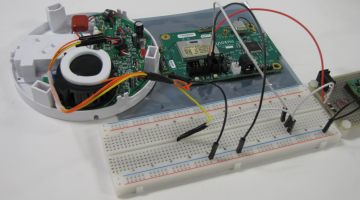
In relation to the entire development process, configuring my RPMA Dev-Kit was by far the easiest part. For the last step, I just had to connect everything together. Using a prototyping breadboard with some jumper wires, I connected the 3.3 volts, ground, and GPIO from the RPMA Dev-Kit to the voltage protection circuit in Figure 2. The final assembled proof-of-concept prototype can be seen in Figure 3.
In a single afternoon, with about twenty-five dollars, I was able to take an off-the-shelf fire alarm to create an LPWAN fire alarm using Ingenu’s RPMA Dev-Kit. The time I saved, during my prototype’s hardware development, then went towards my application’s software development. Using the “Rest2Console” Python script, included in the RPMA Dev-Kit Starter Pack, I was able to create additional Python programs that polled Ingenu’s IntellectTM platform to send alert text messages to whoever might be using my RPMA fire alarm. This project’s rapid time to completion was possible due to the ease of use, simplicity, and independence that the RPMA Dev-Kit offers. Access the Machine Network™ and develop your next great IoT product in this window of opportunity by requesting your own personal RPMA Dev-Kit here today.
Figure 1: Simulated Speaker Output in Blue, Modified Speaker Output in Green

Figure 2: Protection Circuit with Vout Connecting to RPMA Dev-Kit

Figure 3: Completed Proof-of-Concept RPMA Prototype (White = Signal, Red = 3.3 Volts, Black = Ground)


